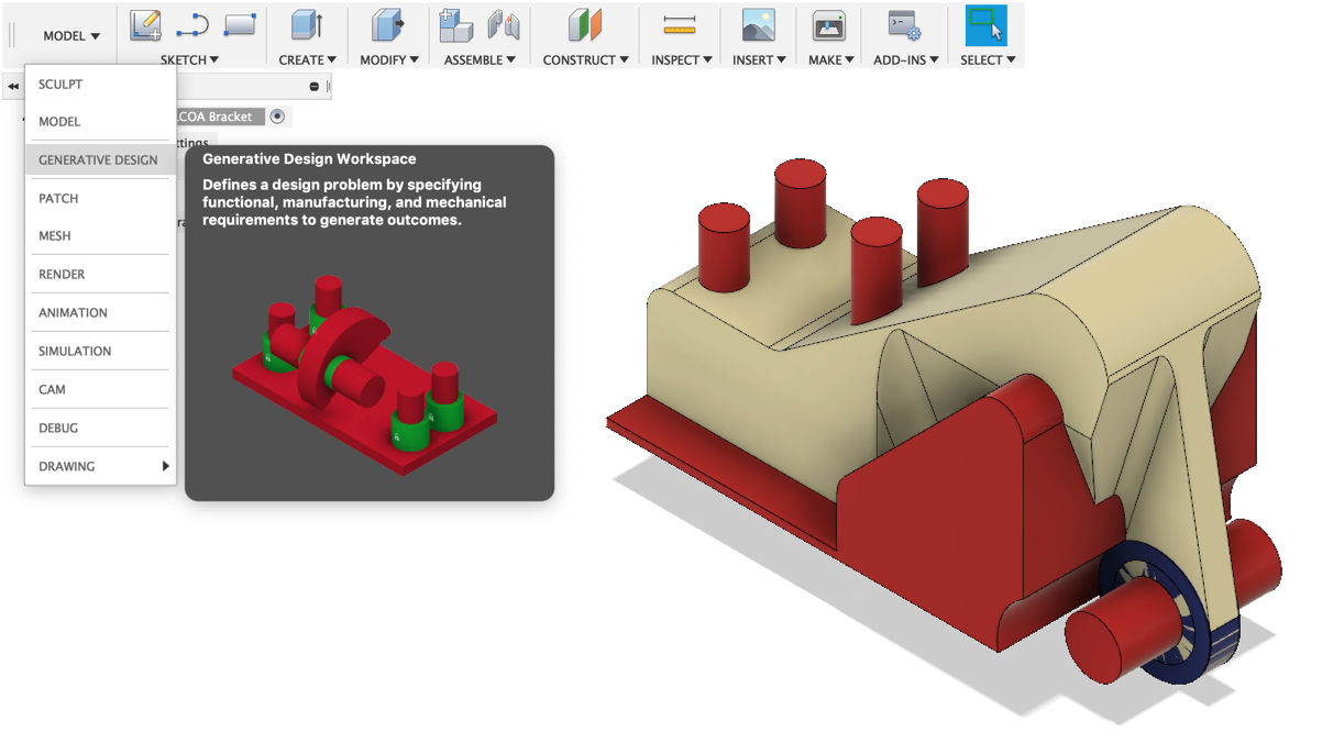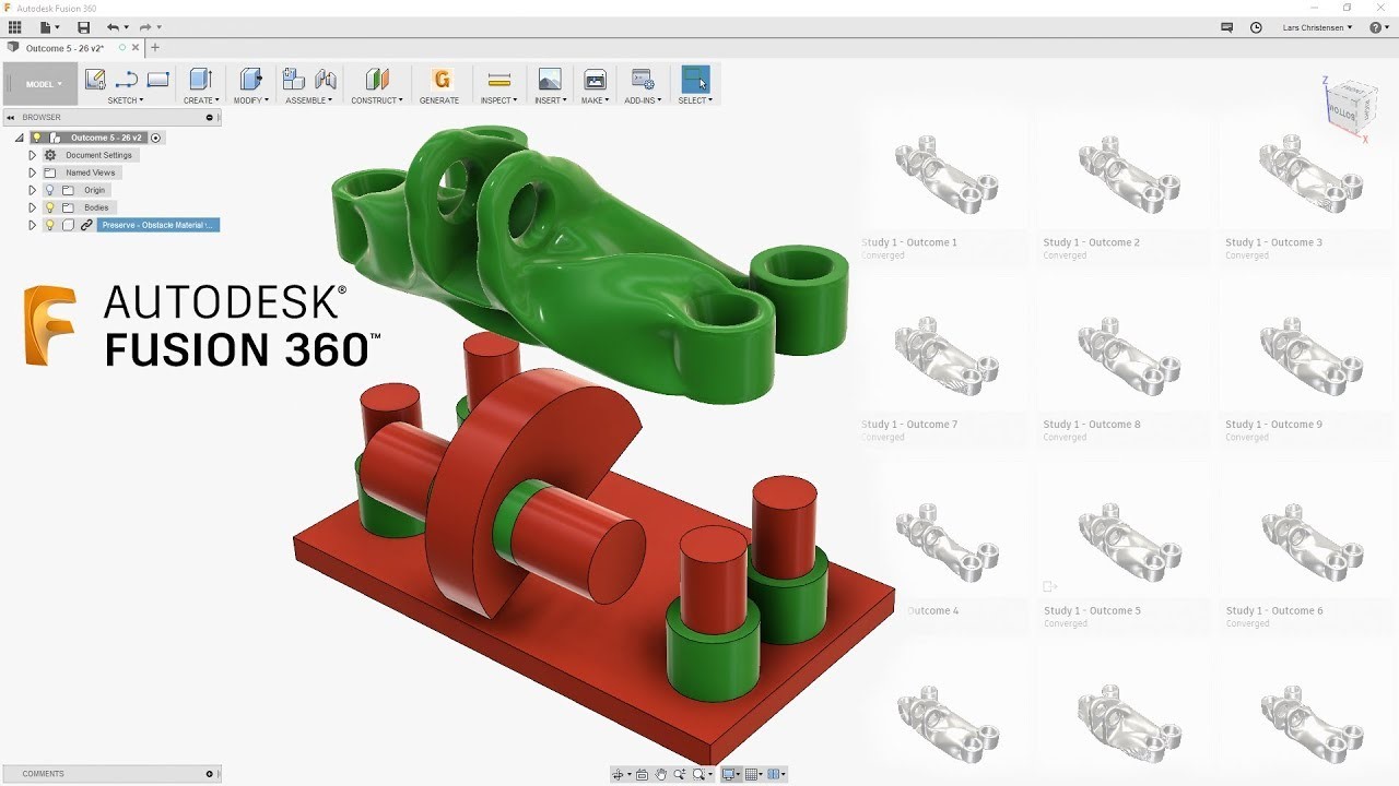

One way around this issue is to roll back a few iterations in the generative process. STL from Fusion 360 and importing it into PrusaSlicer reveals that this unrestricted case is definitely not ideal for 3D printing, with very thin regions which are not printable. As expected, the generative design process does exactly as it is told - minimising the object mass as far as possible whilst keeping the maximum stresses within those allowable for the specified material and safety factor.Įxporting this geometry as a. The final ‘converged’ geometry for the unrestricted case is shown below. It can be seen that the first iteration generates essentially just a solid shape beween the specified bodies, but as the iterations increase, more complex geometry is forming. This means that the geometry will be designed in a way to hopefully produce a part which is not only optimised for the load, but also for manufacture. Instead of asking the user to specify the print orientation in the additive manufacturing setting, the generative design process gives three separate ‘outcomes’ - one for each of the XYZ axis. The generative design process can then be started. It can be seen that the initial geometry is not too dissimilar to my ‘human designed’ arm. A previewer runs the first few design iterations, to allow you to check if the study has any obvious errors. An ‘unrestricted’ case was also run alongside the additive manufacturing one, removing the constraints for 3D printing. The generative design objective was set to minimise stress, with the default safety factor left at 2.00 (a maximise stiffness objective is also available). Within the addditive manufacturing settings, a max overhang angle and mininimum wall thickness can also be set. I have selected PA11 as the material and additive manufacturing and the process. Since generative design in Fusion 360 takes into account the material and manufacturing process, these can also be specified. Here shown by the vertical motor force, and the fixed body mount. The structural loads and constraints can also be added. Next, the essential geometry is set to ‘preserve’ shown in green, and the other bodies are set to ‘obstacle’ in red. To ensure that the generateive design process does not add material in undesired locations, additional solid bodies were created in regions where access is needed - in this case for bolts or nearby components such as the motor and body. The distance between these mounts was also specified. In this case, just the motor mount and the body mount. To start the generative design process, only the essential geometry was created in Fusion 360.

A hole was added for the motor cables, which will not be considered for the following generative design study.

On the left there is a mount for the motor and on the right there is a mount to the drone body.

The arm which I previously designed is shown below. These tests will focus on a small 3D printable drone arm, which I initally designed for the SciRoc autonomous drone competition.
Fusion 360 generative design series#
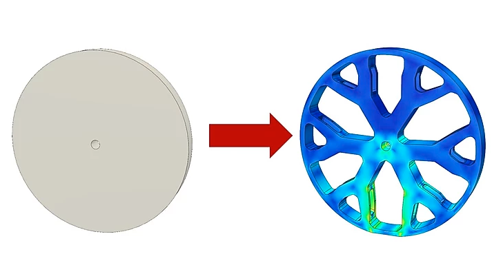
Generative design is an iterative design process that uses artificial intelligence to generate the part geometry, based on a series of input parameters, such as the desired material and manufacturing process - this differs to topology optimisation, which essentially just cuts away regions of the part where the stress is low. This post looks at my initial testing of Fusion 360’s generative design process.


 0 kommentar(er)
